Examine This Report on drilling fluid loss
Wiki Article
Fit diploma amongst the indoor drilling fluid lost control efficiency and field drilling fluid lost control performance
This proactive strategy aids avert stress drops that could lead to fluid loss incidents, represented with the pressure gradient (ΔP) in the wellbore:
This Web site is using a stability assistance to safeguard itself from online assaults. The action you merely done induced the security Option. There are many steps that could set off this block together with publishing a particular term or phrase, a SQL command or malformed knowledge.
Concurrently, arduous administration of solids control devices is critical to take care of the optimal kind and distribution of solids that contribute to a robust filter cake, without compromising other mud Qualities. This proactive, info-driven method, guided from the product, empowers operators to attenuate the financial and operational affect of lost circulation, boosting drilling effectiveness and safety.
Additionally, the leading control factor of your pure fracture form lost control effectiveness is plugging intensity and plugging compactness.
Figure 28. 3D scatter map of the analysis of thief zone site and loss fracture width determined by the response characteristics of engineering parameters.
For fractures of equivalent peak and duration, the affect of wedge-shaped fractures with distinctive inlet/outlet width ratios to the loss conduct of drilling fluid is explored by maintaining the fracture inlet width regular and shifting the fracture outlet width. As proven in Determine 22, the numerical simulation final results of drilling fluid loss in wedge-formed fractures using an inlet width of five mm and outlet widths of 1–five mm are presented. Beneath the exact same overbalanced strain, the instantaneous loss price of drilling fluid in fractures with distinctive outlet widths is basically the same, plus the curve is really a straight-line phase. The stable loss level and cumulative loss of drilling fluid improve with the rise during the outlet width from the wedge-shaped fracture, and the slope of the curve step by step decreases (Determine 22a). The difference between the inflow and outflow of drilling fluid and the full volume transform from the drilling fluid (transform in liquid amount height) are widespread techniques to identify drilling fluid loss. Comparing the engineering logging info when unique losses manifest, it's discovered that, once the Preliminary difference between the inflow and outflow of drilling fluid is equal and afterwards step by step differentiated, the wedge-formed fracture with equivalent inlet width and unequal outlet width may very well be among the triggers of this phenomenon. In step with the pattern of BHP alterations, the adjust in standpipe strain reflecting the severity of loss will increase with the increase in outlet fracture width (Figure 22b,c).
The scatter plots in Figure fifteen drilling fluid technology further exhibit the precision of the AdaBoost design, While using the relative error distribution carefully aligned with the x-axis. These visualization manners set up a strong correlation amongst the particular mud loss knowledge and the final results attained from your AdaBoost, underscoring its precision and trustworthiness.
By implementing the Losseal Max remedy, serious mud losses were being reduced from 80 m³/h to 4 m³/h, enabling the operator to continue drilling within a fractured carbonate reservoir.
In unmanageable disorders, sidetrack above the loss zone to resume drilling in a very stable trajectory.
Establish the reduction in hydrostatic head and reduce the Lively technique to this calculated equivalent mud pounds. Checking the hole pretty carefully for feasible well control challenges is essential.
In the inlet, a specified fluid velocity is applied in accordance with the genuine drilling pumping amount on web site. Soon after reaching The underside with the properly with the rotating drill pipe, a lot of the drilling fluid is lost in the formation through fractures, though the remainder of the drilling fluid is returned to the bottom from the annulus to simulate the true drilling circulation and loss process. The fracture outlet is taken into account a relentless-strain outlet with a value equivalent for the development pore force. The drill pipe surface area, wellbore, and fracture wall are all no-slip partitions, and irregular undulations and friction on the wellbore and fracture wall are simulated by environment roughness constants.
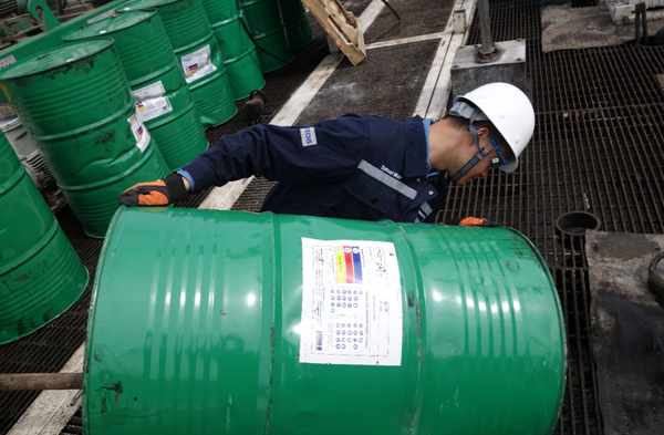
This graphic illustrates the different types of drilling fluids described in the paper, specially how adjusting fluid density (e.g., including barium sulfate) allows preserve strain equilibrium. It supports The purpose about utilizing heavier fluids to mitigate fluid loss pitfalls
The outcome exhibit which the lost control performance of the plunger drilling fluid using a fracture peak of 18 mm is in the very best arrangement with the field benefits, plus the analysis results of the drilling fluid lost control efficiency is “excellent.�?The lost control effectiveness in the plunger drilling fluid by using a fracture peak of 10 mm has the lowest agreement with the field final results, along with the evaluation result of the drilling fluid lost control efficiency is “average.